The Illusion of the Silver Bullet
The dashboard goes red in seconds
It's the largest product launch of the year. Months of work by development, marketing, and operations converge on one event. Your campaign is live, thousands of users click your link, and within seconds your monitoring dashboard turns red. The application is unavailable — users see slow spinners or HTTP 504 Gateway Timeout errors.
Your engineering manager exclaims, "Deploy OCI Load Balancer right away! Increase the shape size, attach it to the public subnet, and add all of our web instances into the backend pool!" The team moves quickly — they deploy the Oracle Cloud Load Balancer, modify DNS records, and distribute load between three identical web servers.
Minutes later, the site is still down. Users are still hitting brick walls. The load balancer itself is completely healthy, its green indicator shining brightly in the Oracle Cloud Infrastructure console, yet it is doing nothing more than efficiently distributing broken connection attempts and database timeouts across an architecture that has fundamentally collapsed underneath it.
This nightmare scenario plays out in enterprise environments every single day. There is a deep-seated, persistent myth in the cloud engineering community that adding a load balancer to an environment automatically achieves high availability in OCI. It does not.
A load balancer is an exceptional traffic cop. It is incredibly efficient at directing vehicles, managing bottlenecks, and steering drivers away from blocked roads. However, if the road it sends the cars down terminates at a collapsed bridge, or if the destination city has run completely out of resources, the traffic cop cannot fix the systemic failure.
A load balancer distributes traffic; it does not repair architecture. If your application code is unscalable, if your database is a single point of failure (SPOF), if your sessions are locked to local server memory, or if your network configurations are fundamentally broken, adding a load balancer will only accelerate how cleanly your system fails.
To build a genuinely resilient cloud ecosystem, we must stop viewing the load balancer as a magical cure-all and start understanding it as a single component within a highly synchronized, meticulously planned OCI network architecture. This guide breaks down how the OCI Load Balancer operates, why it cannot compensate for flawed architecture, and how to design an end-to-end, resilient production environment that stands up to massive scale.
A load balancer is a traffic distribution layer, not a substitute for redundant databases, stateless design, or proper VCN segmentation.
Superficial TCP health checks can show green while your application returns HTTP 500/503 — deep HTTP checks are non-negotiable.
True high availability VCN architecture spans fault domains, stateless apps, database redundancy, and OCI Autoscaling together.
Understanding the OCI Load Balancer Architecture
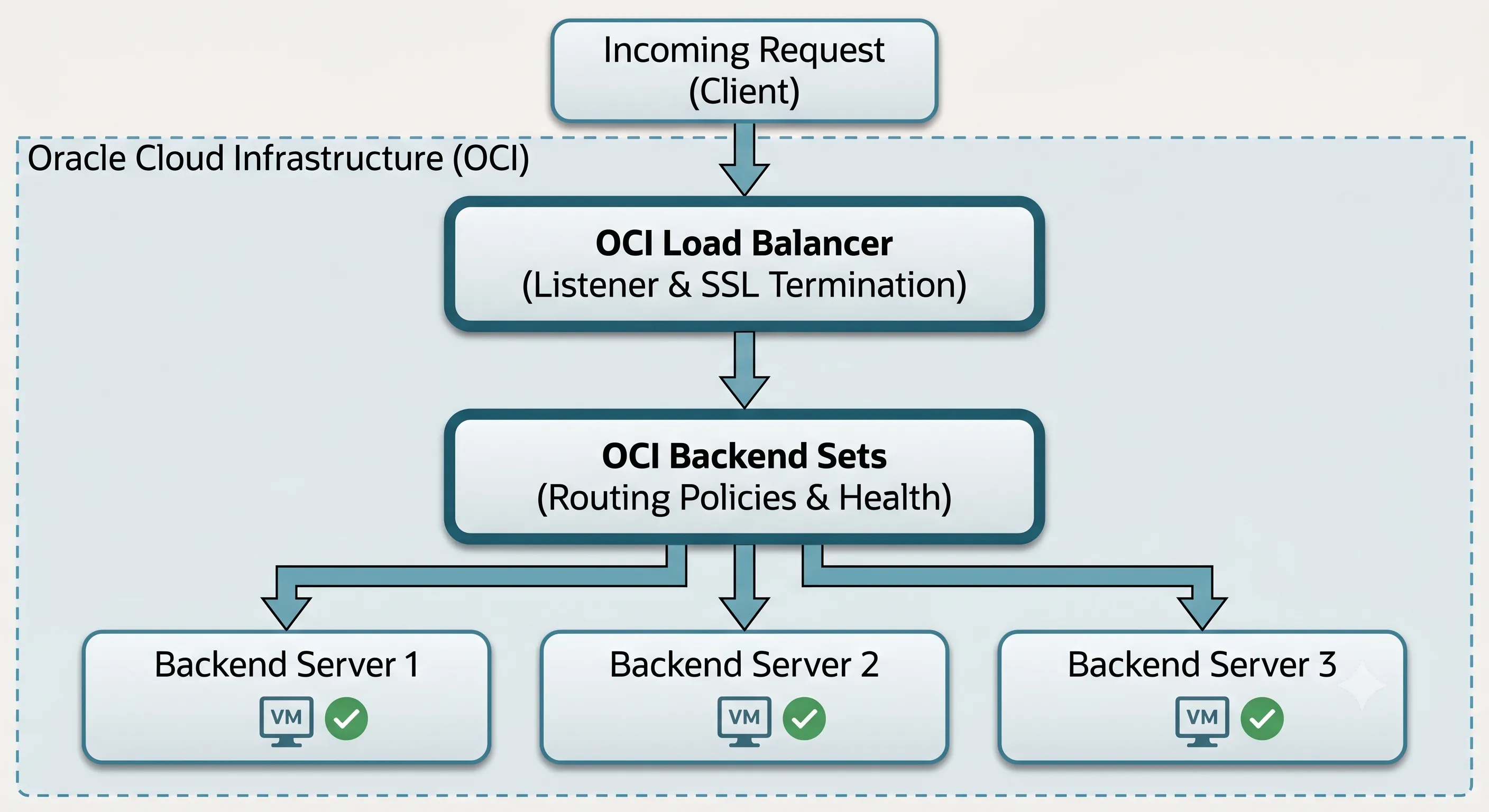
Definition: The OCI Load Balancer is a fully managed, highly available regional service that acts as the single point of entry for client traffic — terminating connections at the frontend, applying routing rules, and forwarding requests to backend compute instances.
The Mechanics of a Managed Load Balancing Service
Unlike traditional legacy environments where network teams had to manually provision, patch, license, and cluster physical or virtual load balancing appliances, OCI abstracts the underlying infrastructure completely. When you deploy a load balancer in OCI, the platform automatically provisions a redundant pair of active-passive or active-active underlying nodes across different Fault Domains or Availability Domains within the region. If the primary node undergoes maintenance or suffers a hardware failure, OCI executes an instantaneous OCI active-passive failover to the standby node without any disruption to your incoming traffic or change to your public IP address.
At its core, the load balancer acts as the single point of entry for your application's clients. It intercepts incoming traffic, terminates the connection at the frontend, evaluates the request against predefined rules, and opens a new connection to a backend server to fulfill the request.
Architecture Diagram: OCI Managed Load Balancing Node Failover Workflow
Protocol Support: Layer 4 vs Layer 7
One of the most critical decisions a cloud network engineer must make is choosing the OSI layer at which the load balancer will operate. The OCI platform offers both options, and mixing them up can lead to massive optimization and security issues.
Layer 4 (Network/Transport Layer)
Layer 4 load balancing routes traffic based strictly on protocol, target IP addresses, and port numbers (TCP or UDP) — without inspecting packet payload data.
How it works: A client initiates a TCP connection, the load balancer applies its routing policy (like Round Robin), selects a backend server, and forwards the packets.
Performance: Layer 4 load balancing requires minimal CPU overhead because it does not decrypt or read the data payload. It is exceptionally fast and capable of handling raw, massive streams of traffic.
Limitation: It cannot perform intelligent routing based on application state, content, or user attributes.
Layer 7 (Application Layer)
Layer 7 load balancing terminates SSL/TLS, inspects HTTP headers, cookies, query parameters, and URL paths, and applies sophisticated content-based routing rules.
How it works: The load balancer terminates the SSL/TLS connection from the client, reads the HTTP request headers, cookies, query parameters, and URL path, and applies sophisticated routing rules.
Intelligent Routing: It can route requests for example.com/api/v1 to a specialized microservices backend set, while routing requests for example.com/static to a storage-optimized web server pool.
SSL Termination: Layer 7 load balancers handle the CPU-heavy task of decrypting incoming SSL/TLS traffic. This process, known as SSL termination, offloads the cryptographic workload from your backend servers, allowing them to dedicate 100% of their compute power to executing application logic.
| Feature | Layer 4 | Layer 7 |
|---|---|---|
| Routing basis | IP, port, protocol | URL path, headers, cookies |
| SSL/TLS | Pass-through (encrypted) | Termination at load balancer |
| CPU overhead | Low | Higher |
| Best for | Raw throughput, non-HTTP protocols | HTTP/HTTPS, microservices routing |
Core Components inside the OCI Console
To configure an OCI Load Balancer effectively, you must understand its three internal architectural pillars:
- Listeners
- A logical entity that listens on a specific IP address, protocol, and port for incoming client traffic (e.g., listening on Public IP 192.0.2.1 on port 443 for HTTPS traffic). You attach SSL certificates directly to the listener for Layer 7 termination.
- Backend Sets
- A logical configuration group that defines a collection of backend servers, the primary load balancing routing policy, and the specific health check parameters used to determine server viability.
- Backends (Backend Servers)
- The actual compute instances or IP addresses attached to a backend set that receive and process the forwarded application traffic.
Public vs Private OCI Load Balancers
Definition: A Public Load Balancer faces the open internet with a globally routable IP; a Private Load Balancer operates entirely within your VCN using an internal RFC 1918 address.
When architecting your network topology within an OCI Virtual Cloud Network (VCN), you must carefully choose between provisioning a Public Load Balancer or a Private Load Balancer. Deploying the wrong type in the wrong subnet tier can open catastrophic security vulnerabilities or completely isolate your services from legitimate users.
Public Load Balancer
A Public Load Balancer is explicitly designed to face the open internet.
- Network Positioning: It must be deployed into a Public Subnet within your VCN. The subnet must be connected to an OCI Internet Gateway, and its route tables must direct internet-bound traffic (0.0.0.0/0) through that gateway.
- IP Allocation: OCI automatically provisions the load balancer with a globally routable, public IP address (or a pair of public IPs if configured across multiple Availability Domains).
- Primary Use Cases: Serving as the internet-facing ingress point for external web applications, content delivery APIs, or public-facing e-commerce storefronts that populate the OCI Web Tier.
Private Load Balancer
A Private Load Balancer is completely hidden from the public internet.
- Network Positioning: It is deployed directly into a Private Subnet within your VCN. It does not require, and actively rejects, any direct path from an Internet Gateway.
- IP Allocation: OCI assigns it a private IP address drawn directly from the internal CIDR block of its hosting subnet.
- Primary Use Cases: Managing traffic internal to your application stacks — such as distributing traffic between the OCI Web Tier and the underlying OCI Application Tier, balancing API requests across microservices, or isolating secure backend database access points.
| Architectural Feature | Public Load Balancer | Private Load Balancer |
|---|---|---|
| Subnet Requirement | Public Subnet exclusively | Private Subnet (Highly Recommended) |
| IP Address Type | Globally routable Public IP | Internal Private IP (RFC 1918) |
| Internet Accessibility | Accessible via the open internet | Accessible via VCN, Peered VCNs, or VPN |
| Typical Architectural Tier | Edge / Ingress Layer (OCI Web Tier) | Internal App Tier / Microservices |
| SSL/TLS Handling | Decrypts public internet traffic | Handles internal corporate transit security |
Never expose your application servers or databases directly to the public internet. The standard enterprise pattern for OCI network architecture best practices is to place a Public Load Balancer in a public subnet to handle internet ingress and terminate SSL, forward that traffic to web compute instances isolated inside a private subnet, use a Private Load Balancer to route communication between those web instances and your internal application processing instances, and isolate your database layer completely in the deep backend.
Configuring OCI Backend Sets for Scale
Definition: An OCI Backend Set is the configuration group that defines which compute instances receive traffic, which routing algorithm distributes requests, and how health checks determine server viability.
An OCI Load Balancer is only as smart as the OCI Backend Sets you configure for it. A backend set defines the operational rules governing how traffic moves from the listener down to the actual compute instances executing your code.
Load Balancing Routing Policies
When traffic hits a backend set, the load balancer needs an algorithmic method to decide exactly which server gets the next request. OCI provides three primary native policies:
- Round RobinThis is the default, standard policy. The load balancer goes down the list of healthy backend servers sequentially, sending request 1 to Server A, request 2 to Server B, request 3 to Server C, and request 4 back to Server A. Use it when all backend compute instances are configured with identical hardware specs and your application requests consume roughly the same amount of processing time.
- Least ConnectionsThe load balancer actively tracks the number of open, concurrent active connections on every backend server. When a new request arrives, it routes it to the server currently handling the lowest volume of active sessions. Use it when processing time varies widely — for example, if some users download massive 500MB reports while others load a 2KB profile fragment.
- IP HashThe load balancer takes the client's source IP address and applies a hashing algorithm to map it to a specific backend server. As long as the client's IP remains unchanged, all subsequent requests route to the same backend instance. Typically used as a fallback mechanism for stateless applications requiring primitive session continuity at the network layer.
Session Persistence: The Stateful Architecture Trap
One of the single greatest architectural failures cloud engineers execute is relying on a load balancer's Session Persistence (sticky sessions) to keep a broken, stateful application alive.
When an application is "stateful," it stores user session data — such as items added to a shopping cart, login states, or multi-step form progress — directly in the local RAM or local disk storage of the specific server that handled the initial login request. If the load balancer blindly routes the user's next click to a different server, that new server will have no record of the user's session.
To fix this at the network layer, engineers enable Cookie-Based Session Persistence on the OCI Backend Sets. The load balancer injects a specific tracking cookie into the HTTP response header or reads an existing application cookie, ensuring the user stays glued to Server A for the lifetime of their session.
Relying heavily on sticky sessions creates a fragile illusion of high availability. If Server A suffers a sudden hardware failure, crashes due to an out-of-memory error, or is restarted, the user's session data stored in that server's RAM vanishes instantly. When the load balancer executes an OCI failover and routes the next request to Server B, the user's shopping cart is gone, their login state is wiped, and their transaction fails. The load balancer successfully redirected the network packet, but your bad architecture ruined the user experience.
Implementing Resilient OCI Health Checks
Definition: An OCI health check is a continuous, automated probe executed by the load balancer to verify whether a backend server can actually process application traffic — removing failed instances from the routing pool before users encounter errors.
If routing policies are the brains of a load balancer, Health Checks are its central nervous system. Yet, they remain one of the most misunderstood and poorly configured features within OCI networking.
A health check is a continuous, automated test executed by the load balancer's health check engine to verify whether a backend server is actually capable of processing application traffic. If a server fails the test, the load balancer flags it as unhealthy and stops routing client traffic to it. When the server recovers and passes subsequent checks, it is smoothly reintroduced to the active pool.
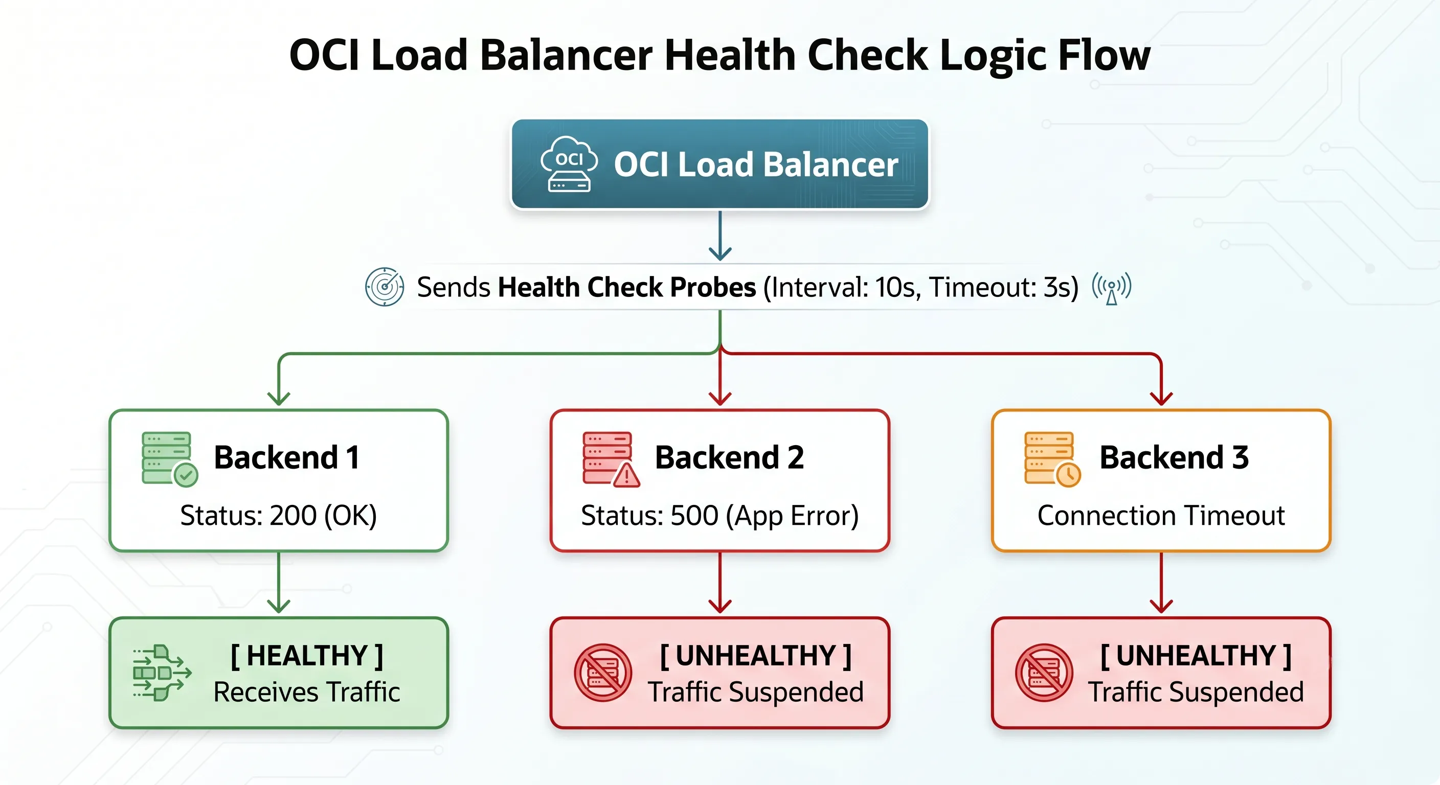
Architecture Diagram: OCI Load Balancer Health Check Probe Workflow
The Critical Configuration Variables
When configuring health checks, you must explicitly tune five critical variables. Leaving these at default values without aligning them to your application behavior is a recipe for system downtime:
- Protocol
- Specify whether the check is executed via TCP, HTTP, or HTTPS.
- Port
- The network port on the backend instance the health check will hit. This does not have to match the application port, allowing you to use dedicated administrative endpoints.
- Interval
- The amount of time between consecutive health check probes (e.g., check every 10 seconds).
- Timeout
- The maximum amount of time the load balancer will wait for a response before marking that specific probe as a failure (e.g., wait 3 seconds max).
- Retries (Failure Threshold)
- The number of consecutive times a health check probe must fail before the load balancer officially marks the instance as unhealthy and removes it from the routing rotation (e.g., fail 3 times consecutively).
The Danger of Superficial TCP Health Checks
The most common mistake engineers make is setting their health check protocol to TCP on port 80 or 443 just because it is simple to configure.
A TCP health check is a simple handshake. The load balancer sends a SYN packet to the backend server, the server responds with a SYN-ACK, and the load balancer responds with an ACK. The connection is open, the handshake is successful, and the load balancer says, "Excellent! This server is perfectly healthy. Send it traffic!"
However, consider what happens if your underlying Apache or Nginx web server process is running fine, but your backend application code has completely locked up, your database connection pool is completely exhausted, or a critical upstream internal API is throwing catastrophic HTTP 500 Internal Server Errors. The operating system's network stack will happily complete the TCP handshake on port 80, but any real user routed to that instance will receive an un-rendered page or a broken application error.
Your load balancer thinks the environment is flawless, while your users are experiencing total system downtime.
Implementing Deep HTTP Application Health Checks
To achieve true resiliency, you must implement deep, application-aware HTTP/HTTPS health checks. Instead of checking a generic port or a static text file (health.txt), configure your developers to build a dedicated, secure health check endpoint within the application framework (e.g., /healthz or /api/v1/status).
When the load balancer queries /healthz, the application code should internally execute a series of diagnostic self-tests before responding:
- Can I successfully open a quick query to the database?
- Can I read/write to the shared storage directory?
- Is the local file system below 95% capacity?
- Are my critical downstream microservices responding?
If all internal criteria are met, the endpoint should return an explicit HTTP 200 OK status code. If any critical component is failing, it should return an HTTP 503 Service Unavailable code. You configure the OCI Load Balancer backend set to explicitly look for an HTTP status response of 200. The moment the internal tests fail, the load balancer automatically pulls the compromised server out of service before a single user ever encounters an application error.
Common Misconceptions: Deconstructing Architectural Myths
To fix bad architecture, we must first confront the deep misconceptions that lead engineers into a false sense of security. Let's systematically dismantle the five most pervasive myths regarding load balancers.
- "My application has a load balancer, so it's highly available."The Reality: High availability is a holistic property of an entire systemic pipeline — it cannot be granted by a single edge component. If you place a load balancer in front of a single compute instance, you have zero redundancy. If you place it in front of two compute instances that are both dependent on a single, non-replicated database instance, your database remains a massive Single Point of Failure (SPOF).
- "My database doesn't need redundancy because the load balancer manages traffic."The Reality: A standard Layer 7 OCI Load Balancer manages web and application layer protocol transit (HTTP/HTTPS); it does not manage, route, or balance internal SQL/NoSQL transactional database connections. Redundancy at the database tier requires its own independent architecture — such as Oracle RAC, Oracle Autonomous Database with built-in auto-failover, or Oracle Data Guard.
- "Health checks guarantee 100% application uptime."The Reality: Health checks are reactive, not predictive. If your health check interval is set to 15 seconds with a failure threshold of 3 retries, it will take a minimum of 45 seconds of continuous failure before the load balancer officially recognizes a crashed server. During that window, thousands of user requests will continue to hit the broken instance and fail.
- "A load balancer scales my application automatically."The Reality: A load balancer distributes traffic across the instances currently defined in its backend set; it does not spin up new servers when traffic surges. To achieve dynamic scalability, you must pair the load balancer with an OCI Autoscaling configuration linked to an Instance Pool.
- "Adding more backend servers fixes poor, unoptimized code."The Reality: If your development team has written unoptimized SQL queries that perform full table scans on every page load, or if the application code has severe memory leaks, adding more backend instances behind a load balancer will not save you. The increased concurrency will simply amplify the strain on your database.
High Availability Requires More Than a Load Balancer
True resiliency — the kind that allows an enterprise application to survive the total loss of a cloud data center without dropping a single user session — requires a comprehensive, defense-in-depth approach to infrastructure.
Physical Isolation: Availability Domains and Fault Domains
Oracle Cloud Infrastructure provides two critical layers of physical and logical isolation within its data center infrastructure:
- Availability Domains (ADs)
- One or more isolated data centers located within a single geographical region. Each AD has its own independent power, cooling, and highly redundant network infrastructure. They are physically separated by miles to ensure a natural disaster affecting one AD will not impact others.
- Fault Domains (FDs)
- A logical grouping of hardware and infrastructure within an individual Availability Domain. Each AD contains three distinct Fault Domains. Compute instances placed in different FDs use completely separate physical server racks, independent power distribution units (PDUs), and isolated top-of-rack network switches.
To build an architecture that defies failure, you must distribute your backend compute instances symmetrically across multiple Availability Domains (or across all three Fault Domains in single-AD regions). If a physical server rack undergoes a hardware short-circuit or a power failure inside Fault Domain 1, your instances running in Fault Domains 2 and 3 continue operating without skipping a beat.
The Stateless Application Golden Rule
Stateless architecture treats every incoming request as an entirely isolated event — with all user session state decoupled from local compute and stored in an external, centralized caching tier or database.
To fully unlock the true power of an OCI Load Balancer and allow it to route traffic completely freely without the brittle crutch of sticky sessions, you must design your application tier to be entirely stateless. A stateless application treats every incoming request as an entirely isolated event. The compute instance processing the request carries zero historical memory of the user's previous actions.
To achieve this, all user session states must be completely decoupled from the local compute instances and offloaded into an external, high-performance, centralized caching tier or database tier — such as an OCI Cache with Redis service or a highly available Oracle NoSQL Database.
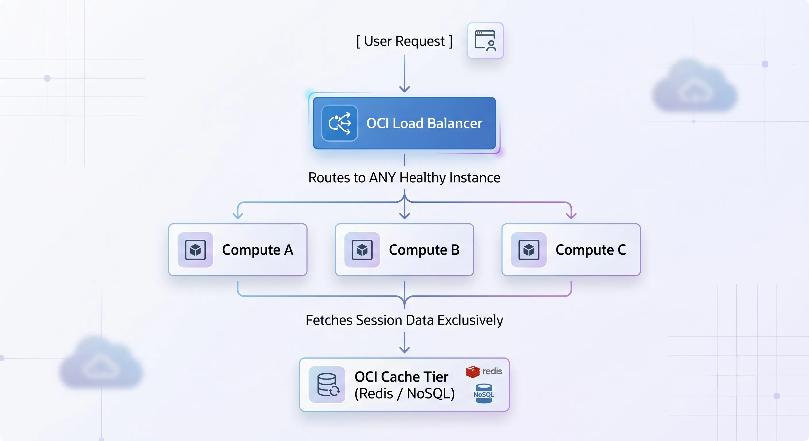
Architecture Diagram: Stateless OCI Application Tier with Centralized Session Cache
When a user logs in, their session token is validated against the central Redis cache. If the load balancer sends request 1 to Compute A and request 2 to Compute B, Compute B simply queries the centralized cache, pulls the user's state, and processes the transaction flawlessly. This architecture allows you to instantly terminate, upgrade, or add hundreds of compute servers at any second without ever disrupting a single active user.
Orchestrating the Full Architecture Stack
A truly resilient ecosystem requires every layer of the cloud stack to play its part in high availability:
- OCI Autoscaling: Tied directly to compute instance pools, allowing horizontal scaling to expand and contract dynamically based on real-time traffic demand.
- Database High Availability: Leveraging Oracle Data Guard to continuously stream real-time transactional logs from a primary database instance in AD-1 to a standby database instance in AD-2, enabling immediate, automated database failover if the primary node goes dark.
- Network Security Groups (NSGs): Serving as granular, instance-level virtual firewalls that restrict traffic so that backend compute instances only accept incoming connections explicitly originating from the private IP addresses of the load balancers.
- OCI Monitoring and Logging: Implementing unified log collection and real-time metric alarms to alert operations teams the exact second health checks begin to degrade, long before the system reaches an unrecoverable failure state.
OCI Load Balancing Best Practices
To ensure your load balancing deployments conform to enterprise production standards, integrate these actionable architectural principles derived directly from the OCI Architecture Best Practices and the Oracle Well-Architected Framework:
- Symmetrically Distribute Across Failure DomainsAlways place your backend compute instances across multiple Availability Domains or Fault Domains. Ensure that the identical application version and environment configurations are deployed symmetrically across all instances in the backend set.
- Segregate Logic via Separate Backend SetsDo not dump all your web paths and different functional services into one massive backend pool. Create distinct backend sets tailored to specific operational profiles. Use Layer 7 routing rules to direct /api traffic to an API-optimized backend set, and /static traffic to a static content server cluster.
- Implement Deep, App-Aware HTTP Health ChecksAvoid lazy TCP health checks. Work directly with your software developers to engineer an intelligent /healthz or /status application endpoint that vigorously validates database connectivity, storage availability, and core execution dependencies before returning an explicit HTTP 200 OK response.
- Enforce Strict Least-Privilege Network IsolationNever attach public IP addresses directly to your application or web compute servers. Keep them isolated inside secure, private subnets. Use a Public Load Balancer strictly as the single internet-facing ingress gateway, and configure your Network Security Groups (NSGs) to reject any incoming traffic that does not originate from the explicit private IP of your load balancer.
- Design for Stateless ScaleDecouple all user session persistence, file uploads, and volatile application states completely away from the local file systems or RAM of individual compute instances. Move state management exclusively into specialized distributed caches (e.g., OCI Cache with Redis) or highly available database tiers.
- Pre-Accustom and Test Failure ScenariosDo not wait for a massive production traffic spike to discover how your architecture handles stress. Continuously execute game-day chaos engineering simulations: manually terminate active compute instances, drop database nodes, and simulate network isolation events to verify that your OCI failover workflows and health check routines respond exactly as designed.
Real Production Example: The Resilient E-Commerce Architecture
To tie all these concepts together, let's analyze a real-world production deployment of a massive, enterprise-grade e-commerce application built on Oracle Cloud Infrastructure. This architecture is designed specifically to survive massive traffic spikes and severe infrastructure degradation without suffering a single dropped checkout transaction.
The Ingress Path: How Traffic Flows Under Normal Operations
When an everyday user opens their browser and navigates to the online store, the request follows a strictly orchestrated, highly secure physical path through the VCN:
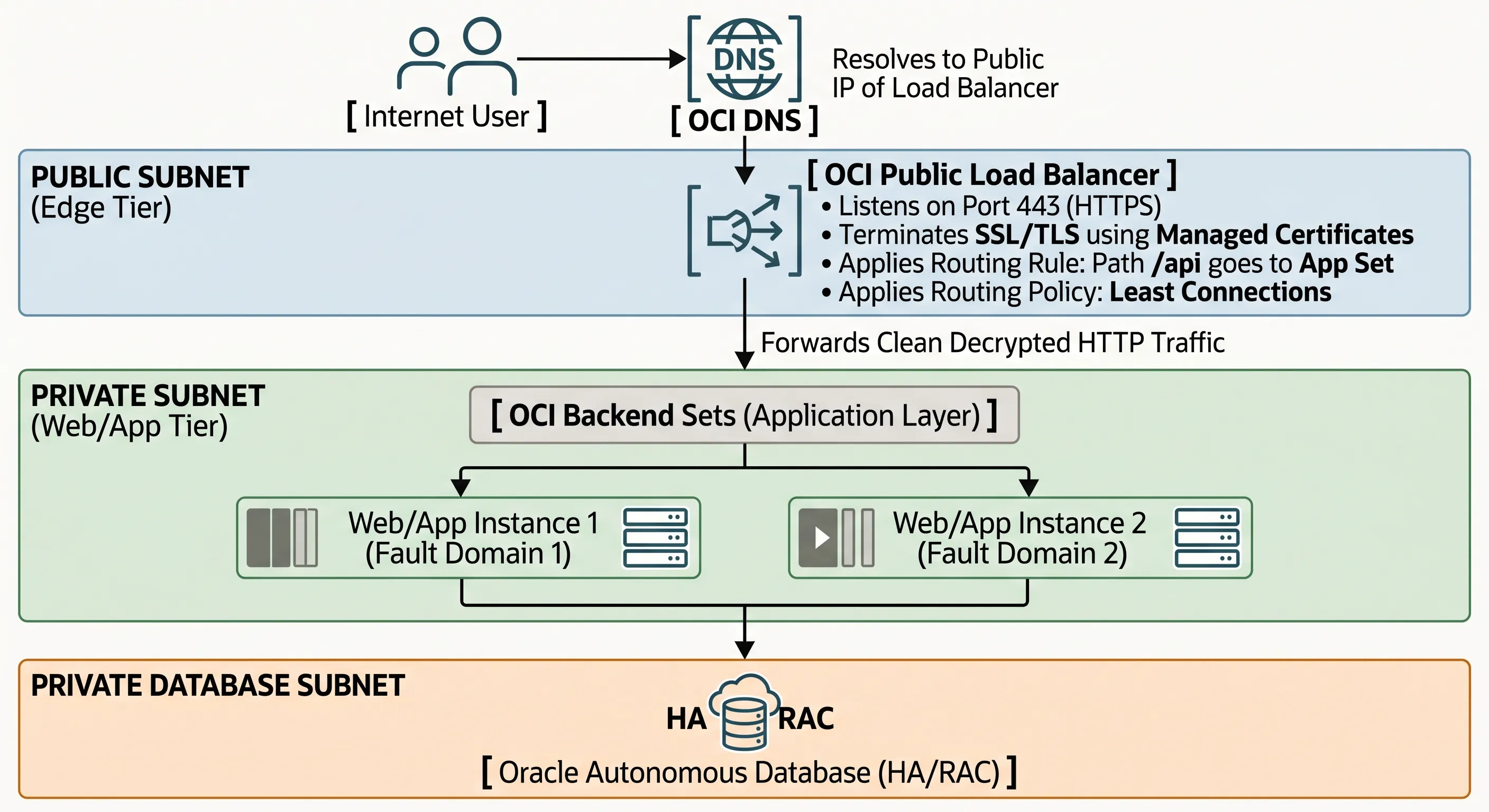
Architecture Diagram: Resilient OCI E-Commerce Traffic Ingress Path
- DNS Resolution: The client's browser queries OCI DNS, which resolves the store's URL to the high-availability Public IP address of the internet-facing OCI Public Load Balancer.
- Edge Ingress & Decryption: The traffic hits the Public Load Balancer situated inside a secure Public Subnet. The load balancer listener intercepts the HTTPS connection on port 443, decrypts the TLS layer using centralized OCI certificates, and inspects the raw HTTP request headers.
- Application Tier Distribution: The load balancer applies a Layer 7 routing policy. It looks at the request and directs it to the appropriate OCI Backend Sets inside the application layer. Using the Least Connections policy, it forwards the unencrypted HTTP traffic across a secure, internal private subnet boundary straight to the compute server currently handling the lightest processing load.
- Stateless Processing & Caching: The compute instance (e.g., Web/App Instance 1, running inside Fault Domain 1) processes the shopping cart transaction. It immediately validates the user's session state by querying a centralized, high-speed OCI Cache with Redis cluster, updates the transactional records inside an Oracle Autonomous Database running in a highly secure, deep private database subnet, and returns the response back through the load balancer to the user.
Failure Mode Walkthroughs: How the Architecture Adapts
Scenario A: A Single Web/App Compute Instance Suffers a Fatal Hardware Crash
The Failure: The physical server rack hosting Web/App Instance 1 inside Fault Domain 1 suffers an instantaneous power failure. The entire operating system crashes instantly.
The Architectural Response: The OCI Load Balancer health check engine is continuously probing the /healthz endpoint of that instance every 5 seconds. Within seconds of the crash, the next probe fails to connect. The engine retries twice more to eliminate temporary network blips. By the 15th second, the failure threshold is hit. The load balancer instantly tags Instance 1 as Unhealthy and isolates it, halting all new incoming user traffic to it.
The User Impact: Because the entire application layer was built strictly stateless, the user sessions were never tied to Instance 1's memory. When the load balancer seamlessly diverts all ongoing traffic to Web/App Instance 2 inside Fault Domain 2, Instance 2 pulls the session tokens out of the central OCI Cache tier. The users clicking through the checkout line experience zero dropped connections, zero errors, and zero data loss.
Scenario B: The Application Code Experiences a Severe Memory Leak and Database Timeout
The Failure: A buggy code update causes Web/App Instance 2 to completely exhaust its internal database connection pool. The server is technically powered on, the Nginx web tier process is running fine, and it readily accepts TCP handshakes on port 80. However, any real user attempting to load the page gets stuck on a white screen that eventually terminates in an ugly database error.
The Architectural Response: If this environment were using a lazy, superficial TCP health check, the architecture would crash entirely, because the load balancer would blindly keep sending thousands of users to that broken instance. However, because our architecture implements a Deep HTTP Application Health Check targeting /healthz, the internal code diagnostic script executes, realizes it can no longer communicate with the Oracle Database backend, and intentionally returns a hard HTTP 503 Service Unavailable status code back to the load balancer probe. The load balancer reads the 503 status, recognizes that the internal application logic is broken, and immediately drops the instance from the active backend pool.
The User Impact: The load balancer successfully protects your users from encountering broken code by isolating the failed server. Simultaneously, the OCI Autoscaling infrastructure detects that the remaining healthy instance is experiencing a massive spike in CPU load due to absorbing the entire traffic volume. It automatically invokes an OCI API call to provision a brand-new, healthy third compute instance inside Fault Domain 3. The new instance initializes, passes its HTTP health checks, and is smoothly registered into the load balancer's backend set, restoring the platform to optimal processing capacity without any human intervention.
The Blueprint for True Resiliency
When your application architecture is broken, brittle, or completely unscalable, relying on a load balancer to save your system is like putting a glossy coat of paint onto a structurally cracked foundation. It might look clean and reliable on your infrastructure dashboard during periods of low traffic, but the exact second a real production surge or a hardware failure hits the environment, the illusion will collapse completely.
A load balancer is an essential, highly powerful component of modern cloud engineering — but it is only a single piece of a far larger puzzle. True high availability is not a commodity you can purchase by checking a box in a cloud console. It is an intentional, end-to-end architectural discipline that must be woven into every single layer of your system design.
Stop using load balancers as an architectural band-aid. Design your core systems to expect, tolerate, and isolate failures at every layer. A load balancer can distribute traffic — but only good architecture can keep your application alive.
To build an application infrastructure that can confidently survive the unexpected, you must eliminate every single point of failure. You must decouple your state away from your compute nodes, enforce strict physical isolation across multiple Availability Domains and Fault Domains, engineer rigorous, deeply intelligent application-aware health checks, and build out automated autoscaling groups that respond fluidly to real-world chaos.
Reader Challenge: Audit Your Infrastructure Today
Take a look at your current production workloads running in OCI or your local test environments and ask yourself these three critical questions:
- Are your load balancer health checks using a superficial TCP handshake, or are they actively validating database and internal application layer health via an HTTP endpoint?
- If one of your primary application servers crashed right now, would your users lose their shopping carts or login sessions because you are relying on sticky sessions?
- Are your compute instances completely isolated inside private subnets, shielded securely behind a dedicated tier of load balancers?
If you don't like the answers to those questions, it's time to step away from the load balancer configuration screen, open up your architecture design board, and rebuild your system for true cloud-native resiliency.